Thanks, Jim. I'm not sure what it is that those college kids, and their instructor, patented or intended to patent. I didn't see anything new there.
I also suspect that their design of four parallel arms parallel to the diamond frame and mounted on it, is much, much heavier for strength than the purer design of two straight, vertically parallel tubes straight across the bike between the front wheels, in which case they could put the two tubes across the bike above the tires so that the outboard pivots fall directly over the centreline of each tyre, which is desirable for tyre longevity; they already have the cost of making up two special spindles, so they might as well have made them longer to put the pivots in line above and over the centre of the tyre. However, even that is unnecessary: If you imagine taking two complete bicycle front ends of a fork with tyre and brake fitted, and the steering tube standing up uncut, you don't need to manufacture spindles: you have them already, and their swivel falls directly above the centre of the tyre's contact patch (or as near as other desirable geometrics dictate). Zero scrub. Magic. Now insert a piece of head tube over each steerer tube and attach in the normal manner with normal bearings and a headset kit and stem, pivot the leaning cross-bike tubes on the two head tubes top and bottom at each side (say on pre-installed studs), and attach the centre of the central upright to the head tube on the diamond frame (ditto), and the suspension is done. For steering attach an arm between each side's stem to the stem on the steerer tube attached to the diamond frame, and you're done -- and you've avoided a whole bunch of manufacturing costs by simply using standard, mass-produced, cheap bicycle parts. In the design solution as I just laid it out, I also think those students could get away with not hard-triangulating the virtual wishbones (in their design they must make four swivelling links very stiffly restrained in the horizontal direction by a heavy choice of materials and fixings or the thing will aim itself and bend all over the place, which will make for surprising steering inputs, to say the least!) by simply making the steering roads a bit stiffer than normal and placing them at the correctly angle -- after all, on a bike, any bike, not just a tilting bike, the steering falls naturally on the centre-line of the bike which is also ground zero for the purest tilting geometry. All the rest is refinement: for instance, at the outer ends of the steering arms a measure of isolation from road irregularities is easily built in by threading the steering rod, fitting a Ford exhaust hanger rubber between large washers, and clamping the rubber in the stem we fitted earlier, now doing duty as an offset steering arm. Voila, isolated steering.
A standard upright diamond frame makes all this much easier to understand and construct than the chimera of a reclining frame and the myriad problems it inevitably brings with it, which all detract from what they're trying to achieve.
I don't see that you need the complications of Ackerman steering if the two front wheels tilt scrub-free and the two front wheels are no further apart than is necessary for stability.
The simplest design for a lean-lockout for parking the bike or holding it at any desired angle, for instance for mounting, which those kids are still looking for, is a quarter of a brake disc plus a calliper with an on-off switch: a common over-centre lever like on quick releases will do the job and needn't weigh much either. Disc quarter fitted to leaning mechanism, caliber fitted to main bike frame, or the other way round in the event that the brake calliper is lighter than the section of brake disc. For those who aren't into leaning bicycles, they have a natural tendency to fall over because that is inherent in their design, and the purer -- less compromised -- the design, the less stiction there is to hold them up, so a mechanical or hydraulic lock is required. What in normal riding holds them up or in a controlled lean is the gyroscopic action of the wheels.
***
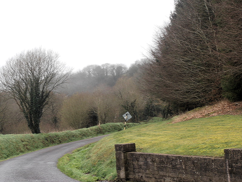
Unfortunately, after giving this enough thought to be able to offer a workable solution, inspection of my lanes leads me to the conclusion that however I scale a tadpole tricycle, it will be the wrong size. Here's a photo of a road I ride often, actually a lane: though it carries two-way traffic, it is only wide enough for one car; even to pass a bicycle, the driver must put two wheels into the ditch.

You can see from the wear on the tarmac that a car pretty much straddles the road. No tricycle will have enough articulation to drop a wheel into the ditch and come out of it again.
Now consider a lane even narrower, well crowned, with a small but irregularly deep ditch on each side, and hedgerows of gorse (thorny enemies of cyclists) brushing the sides of cars. But that isn't the worst of such farm lanes. It's the grass hump in the centre. A wide tadpole type tricycle, in the normal layback position, won't make it up the hills common on such farm lanes. An upright trike will have to be either built wider than optimal in order to straddle the grassy middleman where the central rear wheel will find irregular traction on the central grass when wet, or too narrow to bother with to fit on one track, while the rider will still constantly be in danger of dropping a wheel into the ditch and ending up in the gorse.
Still, it was an interesting mental exercise while it lasted. Thanks to all for thoughts and links.